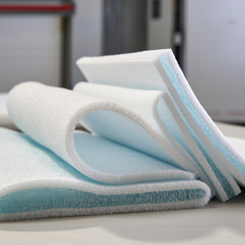
| How the material reduces heat transfer |
| Thermal conductivity (λ) | Many aerogel-fiber blanket products report values around 0.018–0.023 W/(m·K); the actual value depends on product, temperature, density, and test method. | Lower conductivity means less heat flows through a given thickness. Compare products using values measured at similar mean temperatures and under the same test method. |
| Heat-transfer mechanism | Silica aerogel has a highly porous structure; glass fibers provide a flexible reinforcing matrix. | The fine pore structure restricts gas movement, while the solid network and pores limit different paths for heat conduction. The sheet reduces, but does not eliminate, heat transfer. |
| Thickness and thermal resistance | For a material with λ = 0.020 W/(m·K): 10 mm gives R ≈ 0.50; 20 mm gives R ≈ 1.00; 25 mm gives R ≈ 1.25; 50 mm gives R ≈ 2.50 m²·K/W. | Calculated using R = thickness ÷ λ. Increasing thickness increases the insulation layer’s resistance approximately in proportion, assuming the same conductivity and no gaps or compression. |
| Illustrative heat-flow comparison | At a 20 K temperature difference, a 25 mm layer with λ = 0.020 W/(m·K) has an idealized heat flow of about 16 W/m². A 25 mm layer with λ = 0.035 W/(m·K) gives about 28 W/m². | The aerogel example is about 43% lower in this simplified comparison. It assumes one-dimensional steady heat flow through the insulation only; it excludes surface films, joints, fasteners, and thermal bridges. |
| Choosing a sheet for the application |
| Available thickness | Common sheet or blanket formats are product-specific; thickness options may range from a few millimeters to several tens of millimeters. | Choose the thickness from the required thermal resistance and available space. Check the installed thickness, since compression can change performance. |
| Operating temperature | Temperature limits vary substantially by formulation, facing, binder, and installation. Use the supplier’s declared continuous and short-term limits. | Confirm that the sheet, seams, adhesives, and facing are suitable for the highest expected service temperature—not just the aerogel component alone. |
| Moisture and vapor exposure | Water absorption, vapor permeability, and any hydrophobic treatment are product-dependent. | For damp or outdoor conditions, verify moisture data and specify a compatible vapor or weather barrier where needed. Moisture can affect the performance of an insulation assembly. |
| Thickness tolerance and compression | Check declared nominal thickness, tolerance, and any compression or recovery data for the product. | Gaps, crushed areas, and uneven joints can create local heat-flow paths that reduce the benefit of the specified insulation thickness. |
| Handling and installation | Sheets may be cut and fitted with suitable tools; dust-control and personal protective measures depend on the product and its safety documentation. | Follow the product’s installation instructions and safety data. Seal joints appropriately and avoid leaving exposed gaps around edges, penetrations, or fixings. |
| Fire and smoke performance | Fire classification and smoke behavior depend on the complete sheet, including fibers, binders, facings, and coatings. | Request test results for the exact product and intended assembly. Do not infer system fire performance from the aerogel ingredient alone. |
| Verification of thermal data | Common guarded or heat-flow-meter methods include ASTM C518 and ISO 8301; confirm the exact standard, test conditions, and reported mean temperature. | Use comparable, independently tested values where available. A conductivity figure measured under different conditions may not be a direct like-for-like comparison. |
| Project-specific choice | Compare conductivity, required thickness, service temperature, moisture conditions, fire requirements, installation details, and total system cost. | Select the sheet for the complete assembly and operating environment. Product data and project calculations should be checked before specification. |

.svg)