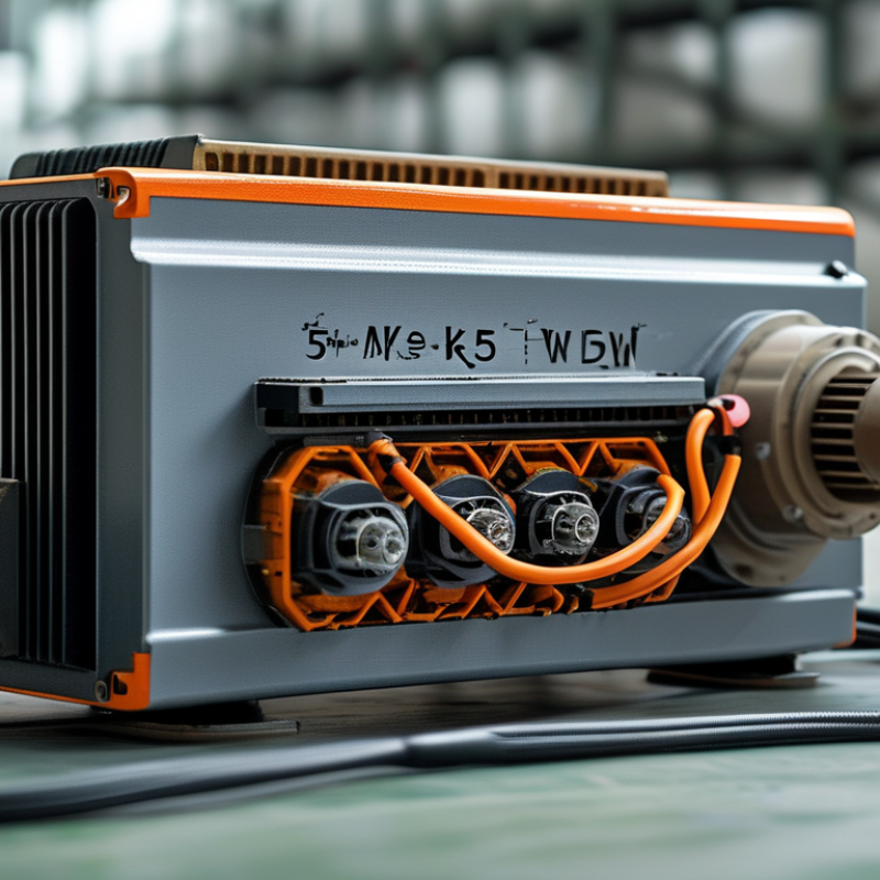
| VFD rated power | 5.5 kW, approximately 7.5 hp | Indicates the intended motor power range under the specified operating conditions. The drive should also be checked by output current, not power alone. |
| Basic operating principle | AC input → rectifier → DC link → inverter using high-speed switching | The VFD converts fixed-frequency AC into variable-frequency, variable-voltage output for motor speed and torque control. |
| Common input configuration | Three-phase, 380–480 V AC, 50/60 Hz; some models also accept three-phase 200–240 V AC | The input voltage and phase arrangement must match the available power supply and the VFD nameplate. |
| Typical continuous output current at 400 V | Approximately 12 A, depending on the model and duty rating | The selected VFD continuous output current must be equal to or greater than the motor nameplate full-load current. |
| Typical continuous output current at 230 V | Approximately 22–24 A, depending on the model and duty rating | Lower motor voltage generally requires higher current for the same power, so current-based sizing is essential. |
| Motor full-load current check | Motor nameplate current ≤ VFD continuous output current | This is the primary sizing rule. A 5.5 kW label does not guarantee compatibility with every 5.5 kW motor. |
| Normal-duty overload capacity | Commonly 110% of rated current for approximately 60 seconds | Suitable for applications with moderate starting and temporary load requirements. The exact rating is model-specific. |
| Heavy-duty overload capacity | Commonly 150% of rated current for approximately 60 seconds | Preferred for conveyors, compressors, mixers, hoists, and other loads requiring higher starting torque. |
| Frequency range | Typically 0–50/60 Hz for standard motor operation; extended ranges may be available | Frequency controls motor speed, but the motor, cooling method, and mechanical system must support the selected speed range. |
| Acceleration and deceleration | Commonly adjustable from a few seconds to several minutes | Longer ramps reduce starting current and mechanical shock; short ramps may require braking or a higher-capacity drive. |
| Motor control methods | V/f control, sensorless vector control, or closed-loop vector control | Vector control generally provides better low-speed torque and speed regulation than basic V/f control. |
| Electronic motor overload protection | Adjustable electronic thermal model based on motor current and operating time | Helps protect the motor from sustained overcurrent when the motor rated current and thermal parameters are configured correctly. |
| Overcurrent and short-circuit protection | Usually provided by the VFD for output overcurrent; upstream fuses or circuit breakers are still required | VFD electronic protection and branch-circuit protection serve different purposes and should not be treated as interchangeable. |
| Overvoltage and undervoltage protection | Typically monitors the DC-link voltage and trips when limits are exceeded | Protects the drive from abnormal supply conditions and regenerative voltage during rapid deceleration. |
| Earth-fault protection | Commonly detects excessive leakage or an output phase-to-ground fault | Provides fault shutdown, but proper grounding, cable insulation, and installation practices remain necessary. |
| Thermal management | Forced-air cooling is common; installation requires adequate clearance and ambient-temperature limits | Excessive heat reduces service life and may cause derating or nuisance trips. |
| Motor cable considerations | Use appropriately rated cable; shielded motor cable may be required for EMC compliance | Long cables can increase leakage current, voltage reflection, and electromagnetic interference. |
| Braking requirement | A braking resistor or regenerative braking unit may be needed for fast stops or high-inertia loads | Regenerated energy can raise the DC-link voltage during deceleration and trigger an overvoltage trip. |
| Recommended selection sequence | 1. Confirm supply voltage and phase; 2. read motor nameplate current; 3. choose duty rating; 4. verify overload, braking, and protection features | This sequence prevents undersizing and ensures that the VFD matches both the electrical supply and the mechanical load. |

.svg)