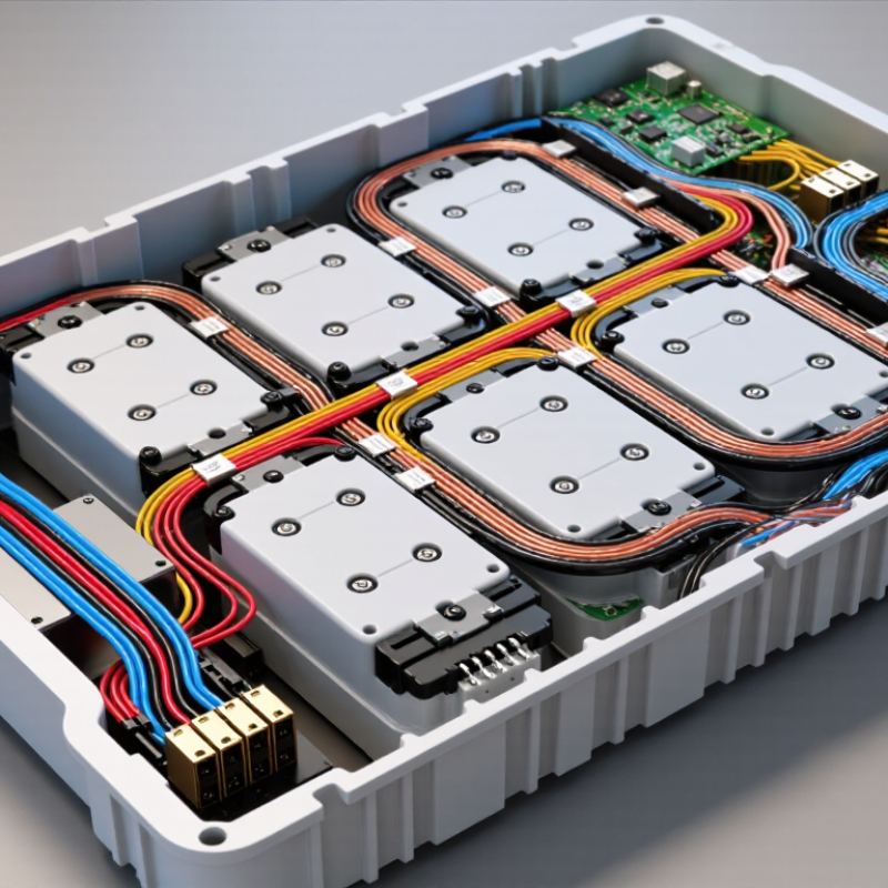
| Definition | A BMS wire harness is an organized group of wires, terminals, connectors, and protective components used to connect a battery management system with a battery pack. | Designed for a specific battery layout, cell count, connector arrangement, and BMS configuration. | It provides the electrical paths required for monitoring, protection, balancing, sensing, and communication. |
| Cell-Tap Wires | Wires connected to the positive and negative terminals of individual cells or series groups. | The number of sensing wires generally corresponds to the number of monitored series groups plus the required pack reference connection. | They allow the BMS to measure individual group voltages and identify overvoltage, undervoltage, or imbalance conditions. |
| Temperature-Sensor Wires | Wires that connect thermistors or other temperature sensors to the BMS. | Common sensor types include negative-temperature-coefficient thermistors; the exact resistance rating depends on the BMS design. | Temperature feedback helps the BMS restrict charging or discharging when the battery is too hot or too cold. |
| Current-Sensing Connections | Connections for a shunt, Hall-effect sensor, or another current-measurement device. | The harness may carry low-level signal wires, power-supply wires, or both, depending on the sensing method. | Accurate current information supports state-of-charge estimation, fault detection, and charge or discharge control. |
| Balancing Connections | The same cell-monitoring leads may be used by the BMS to activate passive or active balancing circuits. | Passive balancing commonly dissipates excess energy as heat; active balancing transfers energy between cell groups. | Balancing helps reduce voltage differences between series groups and supports usable capacity and battery life. |
| Power and Ground Wires | Wires that supply the BMS electronics and provide the required reference or ground connection. | Wire size is selected according to operating current, voltage drop, temperature, insulation rating, and installation conditions. | Correct power connections help prevent unstable operation, overheating, incorrect measurements, and BMS failure. |
| Communication Wires | Wires used to exchange data between the BMS and external devices such as chargers, displays, controllers, or vehicle systems. | Common interfaces include CAN, UART, RS-485, and other manufacturer-defined communication links. | Reliable communication enables monitoring, configuration, diagnostics, and coordinated system control. |
| Connectors and Terminals | Mechanical and electrical interfaces that connect the harness to the BMS, cells, sensors, and other equipment. | Important specifications include pin count, terminal compatibility, contact rating, locking method, and environmental protection. | Correct connector selection reduces loose connections, reversed pins, signal errors, and accidental disconnection. |
| Insulation and Protection | Materials and structures that protect conductors from short circuits, abrasion, heat, moisture, and chemical exposure. | May include abrasion-resistant sleeving, conduit, shielding, strain relief, clips, labels, and insulation rated for the application. | Protection improves electrical safety, mechanical durability, serviceability, and resistance to environmental stress. |
| Wire Routing | The planned physical path followed by the harness inside or around the battery pack. | Routing should avoid sharp edges, high-heat areas, moving parts, excessive bending, and unnecessary proximity to high-current conductors. | Proper routing reduces vibration damage, electromagnetic interference, insulation wear, and installation errors. |
| Polarity and Pinout | The defined assignment of positive, negative, sensing, temperature, communication, and control connections. | Pin order must match the BMS and battery design; wire color alone should not be treated as a substitute for verification. | Incorrect polarity or pin placement can cause inaccurate readings, component damage, short circuits, or safety hazards. |
| Testing and Inspection | Verification of continuity, insulation, connector fit, pin sequence, sensor readings, and resistance to ground where applicable. | Testing should be completed before energizing the battery pack and repeated after installation or service. | Inspection helps detect open circuits, short circuits, reversed connections, damaged terminals, and incorrect assembly. |
| Overall Importance | The harness forms the connection layer between the battery pack and the BMS protection and monitoring electronics. | Its design must match the battery chemistry, series and parallel arrangement, maximum current, environment, and BMS requirements. | A correctly designed and installed harness supports battery safety, measurement accuracy, reliability, maintainability, and system performance. |

.svg)