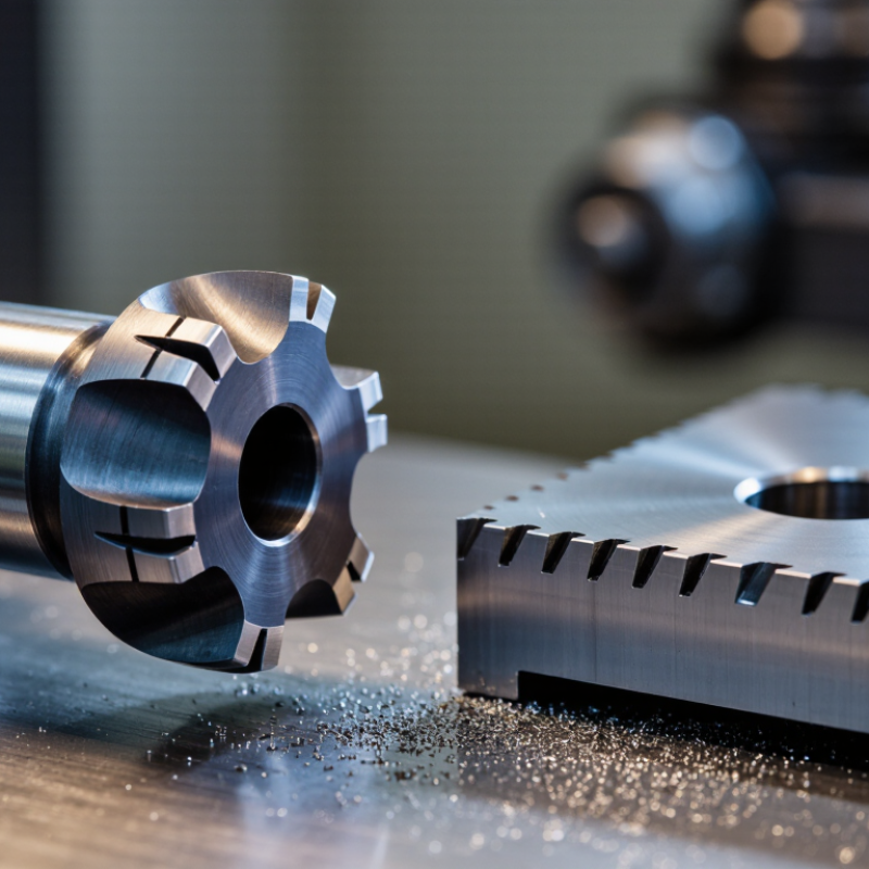
| Single-angle chamfering cutter | Uses one primary angled cutting surface to create a straight chamfer along an external or internal edge. | Edge breaking, deburring, part preparation, and general-purpose milling. | Choose the cutter angle and diameter according to the required chamfer width, access, and workpiece geometry. |
| Included-angle geometry | A 90° included angle commonly produces a 45° chamfer on the workpiece when both sides are symmetrical. | Standard edge chamfers, countersink-style features, and general edge finishing. | Confirm whether the drawing specifies the included angle or the angle measured from the workpiece surface. |
| 30° to 45° cutting angle | Creates a relatively shallow chamfer and is useful where a broad, low-profile edge break is required. | Large edge breaks, visual finishing, clearance transitions, and selected aerospace or fabrication features. | Check tool clearance carefully; a shallow angle may require more radial space to achieve the target chamfer width. |
| 60° to 90° cutting angle | Produces a steeper chamfer and can reach the specified edge size with less lateral tool movement. | Small edge breaks, hole-mouth chamfers, countersinking, and parts with restricted access. | Use when tool access is limited, but verify that the resulting chamfer angle matches the engineering drawing. |
| Solid carbide cutter | High stiffness, wear resistance, and cutting-edge stability; suitable for rigid machine setups and higher cutting speeds. | Hardened steels within the tool’s rating, stainless steels, cast iron, nonferrous alloys, and production milling. | Select based on workpiece hardness, rigidity, flute design, and manufacturer-recommended cutting data. |
| High-speed steel cutter | Generally more tolerant of interrupted cuts and lower machine rigidity, but normally operates at lower speeds than carbide. | General maintenance, low-volume work, manual milling, and softer materials. | Consider HSS when impact resistance, lower cost, or flexible low-speed machining is more important than maximum productivity. |
| Indexable chamfering cutter | Uses replaceable inserts, allowing worn cutting edges to be changed without replacing the complete cutter body. | Repeated production chamfering, large-diameter edge work, and applications requiring predictable insert replacement. | Verify insert angle, corner preparation, clamping security, and the available cutting diameter range. |
| Number of flutes | More flutes can increase feed capacity, while fewer flutes provide more chip space and may improve performance in ductile materials. | The correct choice depends on material, chip formation, coolant use, and required productivity. | Use the tool maker’s chip-load data; do not select flute count independently of spindle speed and feed rate. |
| Workpiece material | Material hardness, abrasiveness, thermal conductivity, and tendency to form built-up edge affect tool life and surface finish. | Common materials include aluminum, copper alloys, steels, stainless steels, cast iron, and engineering plastics. | Match substrate, coating, rake geometry, and cutting parameters to the specific material family. |
| Chamfer width | The required width is controlled by cutter angle, radial or axial depth of cut, and the original edge condition. | Deburring may require a small edge break, while assembly lead-ins and visual features may require a larger chamfer. | Use a test cut or calculation to confirm the actual chamfer width, especially when the angle is not 45°. |
| Machine and setup rigidity | Tool overhang, spindle condition, workholding, and machine rigidity influence vibration, burr formation, and dimensional consistency. | CNC milling, machining centers, manual mills, and multi-axis setups. | Minimize overhang, secure the workpiece, and reduce speed or engagement if chatter appears. |
| Coolant and chip evacuation | Effective chip removal reduces recutting, heat accumulation, built-up edge, and surface damage. | Long chamfering passes, aluminum machining, stainless steel, and deep or partially enclosed features. | Use air blast, mist, or flood coolant according to the material and tool guidance; avoid chip recutting. |

.svg)