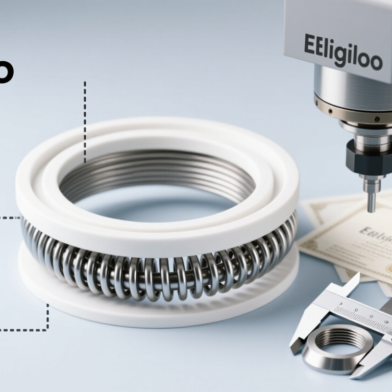
| Seal Construction | Spring-energized PTFE lip seal using a corrosion-resistant cobalt-chromium alloy energizer | Maintains lip contact when PTFE has limited elastic recovery, helping support sealing at low pressure and during thermal cycling | The energizer should remain protected from direct exposure when the process medium or cleaning chemistry is aggressive | Common configuration |
| Primary Sealing Material | Virgin PTFE | Low friction, low moisture absorption, broad chemical resistance, and suitable performance in many static and dynamic sealing applications | Virgin PTFE has lower wear resistance than filled PTFE grades and may require suitable hardware finish, lubrication, or operating limits | General-purpose option |
| Wear-Resistant PTFE Option | PTFE compounded with fillers such as carbon, graphite, glass fiber, or other engineered reinforcement | Can improve wear resistance, dimensional stability, extrusion resistance, or thermal conductivity compared with virgin PTFE | Filler selection changes chemical compatibility, counterface wear, electrical properties, and allowable deformation | Application-dependent |
| Temperature Range | PTFE is commonly used across a broad range, approximately from -200 °C to +260 °C; practical seal limits are design-specific | Supports cryogenic, low-temperature, elevated-temperature, and thermal-cycling applications when properly designed | Actual limits depend on pressure, speed, media, clearance, spring material, installation stress, and the selected PTFE compound | Verify by design review |
| Pressure Capability | Low-pressure sealing is typical; higher pressure may be possible with anti-extrusion support and controlled clearances | Suitable for many actuator, valve, pump, hydraulic, and process-equipment sealing positions | Pressure capability is not determined by material alone. Pressure, temperature, gap, speed, and seal geometry must be evaluated together | Application-dependent |
| Dynamic Motion | Reciprocating, oscillating, and rotary motion can be supported with an appropriate lip profile and surface finish | Useful for shafts, rods, plungers, rotary equipment, and moving actuator components | Control surface roughness, hardness, runout, eccentricity, lubrication, and sliding speed to reduce wear and leakage | Suitable with validation |
| Low-Friction Performance | PTFE provides a low-friction sealing interface compared with many elastomeric materials | Can reduce starting torque, running torque, heat generation, and energy loss in dynamic service | Dry running, poor alignment, excessive lip loading, contamination, and rough counterfaces can still cause rapid wear | Strong advantage |
| Chemical Compatibility | Generally resistant to many acids, bases, solvents, fuels, oils, gases, and process chemicals | Enables use in chemical processing, semiconductor equipment, food-processing machinery, laboratory systems, and general industrial equipment | Check the specific medium, concentration, temperature, pressure, permeation behavior, and exposure duration; PTFE is not universally compatible | Confirm with a compatibility chart |
| Strong Oxidizers | PTFE may perform well in many oxidizing environments, but the full assembly must be evaluated | Can be considered for selected oxygen-service and chemical-service applications when cleanliness and material controls are met | Contamination, high temperature, pressure, ignition sources, and energizer selection may create additional risks; oxygen service requires dedicated qualification | Special qualification required |
| Alkali Metals and Reactive Fluorinating Media | Potentially unsuitable for certain molten alkali metals, elemental fluorine, and highly reactive fluorinating conditions | Identifies media that require alternatives or a formal compatibility assessment before production use | Temperature, concentration, pressure, and reaction conditions can significantly change material behavior | Do not assume compatibility |
| Energizer Material | Corrosion-resistant cobalt-chromium alloy spring or another specified corrosion-resistant spring material | Provides radial or axial loading to maintain contact as the seal moves or experiences thermal changes | Confirm resistance to the process fluid, cleaning agents, sterilization chemistry, and galvanic interaction with surrounding hardware | Specify by media |
| Energizer Geometry | Helical spring, canted-coil spring, U-shaped spring, or other engineered energizer profile | Allows the seal to be tuned for low friction, high sealing force, reciprocating motion, rotary motion, or static service | Spring geometry affects load, friction, installation force, pressure response, and the ability to compensate for wear | Customizable |
| Seal Profile | Single lip, double lip, face seal, radial seal, axial seal, or pressure-assisted profile | Matches the sealing element to shaft, bore, face, rod, piston, valve stem, or flange configurations | Profile selection should reflect pressure direction, movement type, leakage limits, available groove space, and installation method | Customizable |
| Pressure Direction | Unidirectional or bidirectional sealing design | Supports equipment where pressure acts from one side or changes direction during operation | Bidirectional designs may require different lip geometry or energizer loading and should not be substituted without review | Design-specific |
| Size Customization | Inside diameter, outside diameter, cross-section, lip height, groove dimensions, and installation chamfers | Allows integration into standard or proprietary equipment with limited installation space | Provide shaft or bore dimensions, groove drawings, tolerances, pressure, temperature, speed, and assembly direction for accurate sizing | Customizable |
| Surface Finish | Precision-finished mating surface selected for the seal material and motion type | Reduces leakage paths and supports predictable wear behavior | Excessive roughness can abrade the lip; an overly smooth surface may reduce lubricant retention. Use application-specific engineering values | Specify with equipment design |
| Clearance and Extrusion Control | Controlled diametral gap, backup ring, support feature, or pressure-relieving geometry | Helps prevent PTFE deformation and extrusion under pressure or at elevated temperature | Required clearance depends on pressure, temperature, PTFE grade, hardness, geometry, and hardware tolerance | Critical design factor |
| Food and Pharmaceutical Service | Cleanable PTFE seal design with material documentation and appropriate manufacturing controls | Can support hygienic equipment, filling systems, pumps, valves, and process machinery | Regulatory suitability depends on the complete material formulation, spring alloy, processing aids, cleaning agents, and applicable regional requirements | Documentation required |
| Vacuum Service | Low-permeation PTFE profile with suitable spring loading and controlled installation geometry | Can be used in selected vacuum systems, analytical equipment, and process chambers | Evaluate gas permeation, virtual leaks, outgassing, surface condition, pressure differential, and temperature before selection | Vacuum testing recommended |
| Typical Applications | Hydraulic and pneumatic actuators, pumps, valves, compressors, chemical equipment, laboratory instruments, and process machinery | Provides a versatile sealing solution for demanding static and dynamic environments | Application suitability depends on the operating envelope rather than the equipment category alone | Broad industrial use |
| Quality Verification | Dimensional inspection, visual inspection, spring-load verification, leakage testing, material traceability, and batch records | Improves consistency and supports validation for critical sealing applications | Test methods and acceptance criteria should be agreed before production and linked to actual service conditions | Recommended |
| Selection Information Required | Media, concentration, temperature, pressure, motion, speed, shaft or bore size, surface finish, lubrication, leakage limit, and service life | Provides the technical basis for choosing the PTFE grade, profile, spring, and installation dimensions | Incomplete operating data can result in unsuitable material selection or an inaccurate performance expectation | Essential input |
| Engineering note: The values and recommendations above are general selection guidance. Final compatibility and performance depend on the complete seal assembly, operating conditions, installation quality, hardware design, and validation testing under representative service conditions. |

.svg)