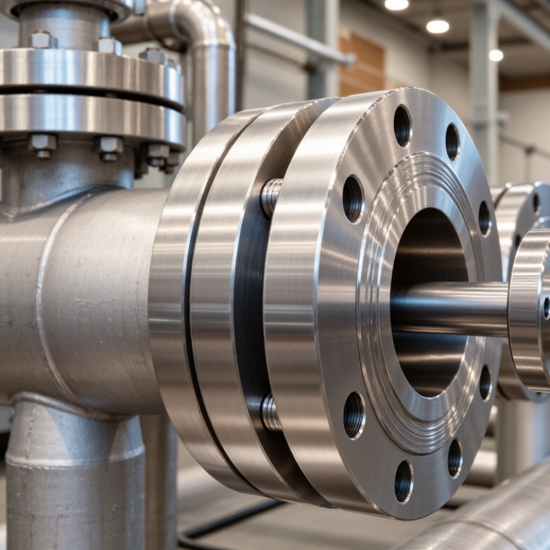
| Definition | A bellows sealed gate valve is an isolation valve that uses a welded metallic bellows around the valve stem to prevent process fluid from escaping through the stem area. | The bellows forms a flexible pressure boundary between the stem and the valve bonnet. The gate moves vertically to start or stop flow through the valve. |
| Primary Function | On-off isolation of pipelines and equipment. | Gate valves are generally intended for fully open or fully closed service rather than continuous throttling, because prolonged throttling can cause vibration, erosion, and damage to the seating surfaces. |
| Main Pressure Boundary | Valve body, bonnet, bonnet gasket, welded bellows, and pressure-retaining bolting or welded joints. | The body contains the line pressure, while the bellows provides a sealed barrier around the reciprocating stem. The bonnet connection may be bolted or welded, depending on the design and service requirements. |
| Bellows Construction | A formed or welded metallic convoluted element designed for axial movement. | Common bellows materials include stainless steels and nickel-based alloys selected according to temperature, corrosion resistance, pressure, and fatigue requirements. The bellows must accommodate repeated stem travel without premature fatigue failure. |
| Stem Sealing Principle | The bellows is welded or otherwise permanently connected to the stem and bonnet-side structure. | Because the stem does not slide through a conventional packing chamber during normal operation, fugitive emissions through the stem passage are greatly reduced. A secondary packing seal may be included as a backup safety feature. |
| Gate Movement | Linear vertical movement of the gate. | When the handwheel or actuator turns the stem, the stem transfers axial force to the gate. The gate lifts clear of the flow path when open and moves between seats when closed. |
| Common Gate Designs | Wedge gate, flexible wedge, solid wedge, and parallel slide gate. | Wedge designs use inclined seating surfaces to provide shutoff. Parallel-slide designs use parallel seating elements and are often selected for specific thermal or pressure conditions. The final choice depends on service, temperature, pressure, and required shutoff performance. |
| Flow Path | Typically a full-bore or near-full-bore passage when fully open. | A properly sized open gate valve generally produces low pressure loss compared with many throttling valve types. The valve should be fully open during normal flow to minimize seat and gate wear. |
| Secondary Sealing | Packing may be installed above the bellows as an additional containment layer. | The secondary packing is not normally the primary dynamic seal in a bellows-sealed design. It can provide temporary containment if the bellows develops a leak and may support emergency emission-control requirements. |
| Typical End Connections | Flanged, butt-weld, socket-weld, and threaded connections, depending on valve size and service. | Butt-weld and socket-weld ends can reduce external leakage paths in permanently installed process systems. Flanged ends support easier removal and maintenance where plant layout permits. |
| Operating Modes | Manual handwheel, pneumatic actuator, electric actuator, or other compatible actuation systems. | Manual operation is common for smaller or less frequently operated valves. Actuators may be selected for remote operation, emergency shutdown functions, process automation, or high operating torque requirements. |
| Opening Sequence | The stem is rotated or driven to lift the gate away from the seats. | The operator should open the valve gradually and verify that the gate reaches the fully open position. In some systems, slow operation helps reduce pressure transients and mechanical shock. |
| Closing Sequence | The stem drives the gate downward until the seating surfaces contact and isolate the flow path. | Closing force must be sufficient for the specified shutoff condition but should remain within the valve's rated operating limits. Excessive force can damage the stem, seats, actuator, or bellows assembly. |
| Leakage-Control Advantage | Reduced stem emissions compared with conventional packed valves. | The welded metallic bellows eliminates the usual sliding stem-to-packing interface during normal operation. This makes the design suitable for applications where containment of hazardous, toxic, volatile, or high-purity media is important. |
| Temperature Considerations | Temperature capability depends on body, trim, gasket, bellows, seat, and packing materials. | Thermal expansion, cryogenic contraction, fluid compatibility, and bellows fatigue must be evaluated together. A valve should not be selected by pressure rating alone. |
| Pressure Considerations | The applicable pressure rating is determined by the pressure class, material, temperature, and design standard. | Allowable pressure commonly decreases as operating temperature increases. The complete valve assembly, including the bellows and bonnet connection, must be suitable for the intended pressure-temperature envelope. |
| Material Selection | Body materials may include carbon steel, stainless steel, alloy steel, or other pressure-rated alloys. | Trim and bellows materials should be selected for corrosion resistance, erosion resistance, temperature capability, and compatibility with the process medium. Material selection should be verified against the fluid composition and operating conditions. |
| Typical Applications | Chemical processing, petrochemical systems, pharmaceutical production, vacuum service, heat-transfer systems, and applications involving hazardous or volatile media. | The design is particularly useful where external stem leakage must be minimized or where contamination of the process medium must be controlled. |
| Advantages | Low external stem leakage, improved containment, reduced routine packing adjustment, and suitability for clean or hazardous services. | The metallic bellows can provide a durable barrier when correctly designed, welded, tested, and operated within its rated stroke and cycle limits. |
| Limitations | Higher initial cost, larger overall height in some designs, and finite bellows fatigue life. | The valve may require more careful inspection and cycle management than a conventional packed valve. Bellows damage can require specialized repair or replacement of the valve assembly. |
| Maintenance Focus | Inspect the body, bonnet joint, bellows area, stem, actuator, seats, packing backup, and end connections. | Maintenance should include checking for external leakage, abnormal operating torque, stem damage, corrosion, actuator malfunction, and signs of bellows failure. Testing should follow the applicable plant procedure and valve specification. |
| Bellows Failure Indication | Possible signs include leakage into the bonnet cavity, changes in operating behavior, or activation of a monitoring or vent arrangement. | A secondary packing seal may delay external release, so inspection and monitoring arrangements should be considered in safety-critical services. The valve should be isolated and assessed according to the site's safety procedures. |
| Testing Considerations | Pressure testing, seat leakage testing, shell testing, and bellows integrity verification may be specified. | Testing requirements depend on the applicable design, manufacturing, fugitive-emission, and plant standards. Test pressure, duration, acceptance criteria, and test medium should be defined before procurement. |
| Relevant Standards | Commonly referenced standards may include API 600, API 602, ASME B16.34, ASME B16.5, ASME B16.10, and applicable fugitive-emission standards. | The exact standard depends on valve size, pressure class, end connection, material, industry, and regional requirements. The purchaser should specify the required edition and acceptance criteria in the technical specification. |
| Selection Checklist | Review medium, pressure, temperature, size, pressure class, end connection, flow direction, cycle frequency, actuation, emissions requirements, and maintenance access. | Correct selection requires coordination between process, piping, mechanical, materials, safety, and maintenance requirements. The valve should be sized for isolation duty rather than used as a substitute for a control valve. |

.svg)