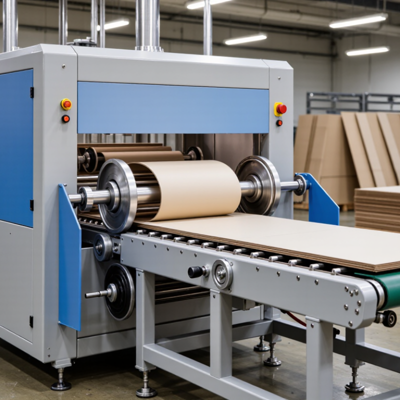
| Machine Definition and Operating Principle |
| Machine Type | Primary purpose | Stationary woodworking machine used to cut straight grooves, channels, rebates, or slots in chipboard panels. | Creates joints, panel recesses, cable routes, back-panel channels, and assembly features. |
| Cutting Method | Material removal | A rotating cutter, grooving saw, or router bit removes a controlled strip of material along a programmed or guided path. | Produces a defined slot width, depth, and position without cutting through the entire panel. |
| Workpiece Positioning | Reference system | Panels are normally positioned against a fence, clamping system, template, or CNC-controlled coordinate system. | Maintains repeatable slot location across batches of furniture or cabinet components. |
| Feed Configuration | Material movement | Manual, semi-automatic, or automatic feed systems may be used depending on production volume and machine design. | Supports prototype work, small-batch production, or continuous industrial manufacturing. |
| Dust Management | Extraction requirement | Local dust extraction is normally connected near the cutting zone to remove wood particles and improve visibility. | Reduces airborne dust, limits contamination, and helps maintain cutting accuracy. |
| Typical Technical Data |
| Compatible Materials | Panel types | Uncoated particleboard, melamine-faced chipboard, laminated particleboard, and some veneered board products. | Used for furniture parts, shelving, cabinet sides, partitions, and interior fittings. |
| Common Slot Width | Cutting width | Approximately 3–20 mm for common panel-grooving operations; the actual range depends on the tool and application. | Accommodates back panels, joining splines, dividers, hardware plates, and service channels. |
| Common Slot Depth | Cutting depth | Approximately 2–12 mm for many furniture and cabinet applications, with depth limited by panel thickness and joint design. | Allows recessed features while preserving the structural body of the panel. |
| Typical Panel Thickness | Workpiece thickness | Approximately 8–40 mm for common chipboard components; heavier industrial equipment may handle thicker panels. | Covers thin drawer components, standard cabinet boards, shelving, and structural furniture panels. |
| Cutting Accuracy | Position and dimension control | Well-maintained CNC or guided equipment can commonly achieve approximately ±0.1–0.3 mm positioning accuracy, depending on setup and material quality. | Supports consistent alignment of dowels, biscuits, connectors, shelves, and cabinet backs. |
| Spindle or Cutter Speed | Rotational speed | Woodworking routing systems commonly operate in the range of approximately 12,000–24,000 revolutions per minute. | Provides the cutting speed required for carbide tools used on engineered wood panels. |
| Production Capacity | Operating mode | Manual machines are suitable for low-volume work, while CNC and automatic systems are designed for repeatable batch or production-line operations. | Improves throughput by reducing repeated measuring, marking, and manual routing. |
| Slotting Workflow |
| 1. Design Input | Drawing or CNC program | Slot length, width, depth, position, feed direction, and tool diameter are defined before machining. | Provides the dimensional reference for repeatable production. |
| 2. Panel Preparation | Inspection and placement | The panel is checked for correct dimensions, surface condition, edge damage, and orientation before being placed on the table. | Prevents incorrect machining and reduces defects caused by damaged or misaligned panels. |
| 3. Clamping | Workholding | Mechanical clamps, vacuum hold-down, or a combination of both secures the chipboard during cutting. | Limits vibration, panel movement, and dimensional variation. |
| 4. Tool Entry | Cut initiation | The cutter enters the panel at the programmed location or follows a mechanical guide and fence. | Establishes the start point and prevents unintended marks on the workpiece. |
| 5. Slot Cutting | Feed and cutting path | The tool travels along a straight or programmed path while removing material to the specified width and depth. | Forms the required groove, channel, or recessed joint feature. |
| 6. Inspection | Quality control | Operators check slot position, width, depth, edge quality, and surface chipping using gauges or measuring tools. | Confirms that the component is ready for assembly or further processing. |
| Industrial Uses |
| Furniture Manufacturing | Cabinets, wardrobes, desks, and shelving | Slots are cut for shelves, dividers, back panels, joining components, and concealed fittings. | Improves assembly accuracy and reduces visible fasteners. |
| Kitchen Cabinet Production | Cabinet carcasses and drawer components | Grooves may be used for cabinet backs, drawer bottoms, connector systems, and alignment features. | Supports modular construction and repeatable cabinet assembly. |
| Office and Commercial Interiors | Partitions, workstations, and storage units | Channels can be machined for cable management, partition components, and removable panels. | Helps integrate electrical and data services into furniture systems. |
| Flat-Pack Furniture | Knock-down components | Precise slots are combined with cams, dowels, biscuits, connectors, or other assembly hardware. | Enables compact packaging and fast on-site assembly. |
| Interior Fit-Out | Wall panels, display units, and built-in storage | Grooves and rebates are used to connect panels and accommodate trims or concealed support parts. | Creates clean lines and repeatable installation details. |
| Retail Fixtures | Shelving and display structures | Repeated slots can receive adjustable shelves, dividers, brackets, or display accessories. | Allows flexible product presentation and component replacement. |
| Automotive and Transport Interiors | Non-structural interior panels | Engineered wood panels may be slotted for trim interfaces, lightweight partitions, or interior fixtures where specified by the design. | Supports accurate fitting of interior components; suitability depends on the approved material and design requirements. |
| Quality, Safety, and Selection Factors |
| Edge Quality | Chipping control | Sharp carbide tooling, suitable feed speed, correct rotation direction, and proper support help reduce breakout on faced chipboard. | Improves the appearance and fit of visible furniture components. |
| Tool Selection | Cutter material and geometry | Carbide-tipped or solid-carbide tools are commonly selected for abrasive engineered wood panels. | Provides wear resistance and stable cutting performance. |
| Panel Surface | Finish protection | Melamine, laminate, or veneer surfaces require correct tool direction, support, and feed settings to avoid surface damage. | Protects decorative faces and reduces rework. |
| Operator Safety | Required controls | Guarding, emergency stops, dust extraction, hearing protection, eye protection, and safe workholding are essential. | Reduces exposure to rotating tools, flying particles, noise, and combustible wood dust. |
| Machine Selection | Key decision criteria | Consider slot dimensions, panel size, required accuracy, production volume, automation level, extraction capacity, and available floor space. | Ensures that the machine matches both the product design and manufacturing workload. |

.svg)