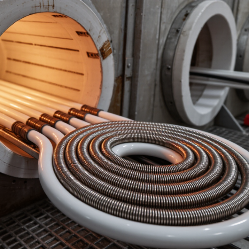
| Tube material | Identify the ceramic tube composition and its specified service temperature, thermal-shock limits, and atmosphere restrictions. | Confirm that the wire’s operating temperature and heater design suit the tube material. Alumina, mullite, and silicon-carbide tubes have different properties and operating limits. | Excessive temperature or rapid temperature changes can damage the tube, regardless of the wire’s own temperature rating. |
| Wire alloy and atmosphere | Check the alloy type and whether the element operates in air, a reducing atmosphere, or another process environment. | Iron-chromium-aluminum and nickel-chromium resistance alloys are used in different high-temperature applications; select based on the element temperature, atmosphere, and supplier data. | An alloy unsuitable for the atmosphere or temperature may oxidize, corrode, or fail prematurely. |
| Tube dimensions and coil fit | Measure tube inner diameter, heated length, element support points, and available clearance for the coil. | Match coil diameter and length to the heater drawing. Allow for thermal expansion and maintain the clearances specified by the system design. | A coil that touches the tube or sags onto a support can create localized overheating, electrical shorts, or mechanical damage. |
| Voltage, power, and resistance | Confirm supply voltage, required power, wiring configuration, and the element’s specified resistance at the stated reference condition. | For a resistive load, use the system design values; basic relationships are P = V × I and, for a fixed resistance, P = V²/R. Check the manufacturer’s resistance and temperature data. | Incorrect resistance or connection configuration can result in underheating, excess current, or electrical overload. |
| Surface loading and coil spacing | Review element surface area, power density, coil pitch, and the heating system’s intended heat-up rate. | Use values established for the alloy, tube geometry, airflow, and process load. Even spacing helps promote more uniform heat distribution. | Excessive local power density or uneven spacing can create hot spots and shorten element or tube life. |
| Terminals and cold ends | Check terminal style, lead material, connection location, and the temperature expected at the terminal area. | Keep connections and cold ends within their rated temperature range, and use compatible electrical connectors and insulation. | Overheated or poorly secured connections can cause resistance increases, arcing, or terminal failure. |
| Controls and operating cycle | Determine whether the system uses on/off control, staged control, or a power controller, and note the expected cycle frequency. | Verify that the element and control equipment are designed to work together. Apply appropriate temperature sensing, over-temperature protection, and ramp limits. | Poor control settings or rapid thermal cycling can stress the wire and ceramic tube. |
| Mechanical support and installation | Review supports, orientation, vibration, expansion allowance, and the installation procedure. | Use supports and clearances specified for the assembly; prevent the coil from being stretched, compressed, or forced against the tube during installation. | Mechanical strain or restricted expansion can deform the element and place stress on the ceramic tube. |

.svg)