| Wire Rope Slings | OSHA 29 CFR 1910.184; ASME B30.9; applicable national lifting regulations. | The rated capacity depends on rope diameter, construction, core, hitch type, number of legs, and sling angle. Use the manufacturer’s marked capacity table; never estimate capacity from diameter alone. | Confirm that hooks, shackles, and lifting points fit the eye size and have compatible rated capacities. Protect the rope from sharp edges and small-diameter bending points. | Legible identification tag, uniform splicing or end fittings, correct rope construction, secure ferrules, and no broken wires, kinks, crushing, bird-caging, heat damage, or corrosion. | Inspect before each shift or use. Remove from service for severe localized wear, damaged fittings, excessive broken wires, distortion, or heat and chemical damage. |
| Alloy Steel Chain Slings | OSHA 29 CFR 1910.184; ASME B30.9; EN 818-4 for assembled chain slings where applicable. | Capacity is determined by chain grade, diameter, number of legs, hitch configuration, and angle. Chain grade markings and the supplied rating chart must be checked before use. | Use only compatible alloy components, master links, shortening devices, and hooks. Do not mix components unless the assembly is approved and rated for the resulting configuration. | Permanent grade marking, traceable identification tag, matching components, properly seated fittings, and no unauthorized welding, heating, or alterations. | Check for stretched, bent, cracked, gouged, or excessively worn links. Do not shock-load, knot, drag, or expose the chain to temperatures or chemicals outside its rating. |
| Flat Webbing Slings | OSHA 29 CFR 1910.184; ASME B30.9; EN 1492-1 for flat woven webbing slings. | Capacity varies with material, width, eye configuration, and hitch type. Straight, choker, and basket ratings are different and must be read from the identification label. | Select a sling wide and long enough for stable load contact. Use edge protection at corners and avoid contact with sharp, abrasive, hot, or chemically reactive surfaces. | Readable label, consistent stitching, protected eyes, even width, and no cuts, burns, melted fibers, pulled stitches, chemical attack, or damaged protective coating. | Inspect the full length before use. Remove immediately if the label is missing or unreadable, or if load-bearing fibers are exposed or damaged. |
| Round Slings | OSHA 29 CFR 1910.184; ASME B30.9; EN 1492-2 for roundslings. | The rated capacity depends on sling construction, hitch type, and angle. The protective jacket is not the load-bearing element, so hidden core damage must be considered. | Use suitable edge protection and ensure the sling is not twisted, bunched, trapped, or loaded over a radius smaller than the specified minimum. | Permanent capacity label, intact jacket, even diameter, secure eyes, and no cuts, snags, heat damage, contamination, or exposed core fibers. | If the jacket is damaged enough to expose or possibly damage the core, remove the sling from service. Do not tie knots or use a damaged sling with a reduced rating. |
| Shackles | ASME B30.26; ASTM A354 or equivalent material requirements where specified; applicable lifting regulations. | Use the marked working load limit for the shackle type and configuration. Side loading, sling angles, and multiple-leg arrangements can reduce the allowable capacity. | The pin diameter and bow must accommodate the sling without binding. Load the shackle in line whenever possible and prevent the pin from contacting the load. | Permanent WLL and size markings, correct pin, uniform body shape, clean threads, and no cracks, gouges, excessive wear, bending, or unauthorized repairs. | Verify that the pin is fully engaged and secured. Do not replace a shackle pin with a bolt or use a shackle with illegible markings. |
| Eye Bolts and Lifting Points | ASME B30.26; ASME B18.15 for forged eyebolts; manufacturer installation instructions. | Capacity depends on design, thread engagement, mounting orientation, and loading direction. Shoulder eyebolts generally require full seating against the load and straight-line loading unless specifically rated otherwise. | Match thread diameter, pitch, grade, and engagement length. Check that the base material and tapped hole are strong enough for the intended load. | Clear WLL and orientation markings, undamaged threads, correct shoulder contact, sound mounting surface, and no bending, cracks, corrosion, or deformation. | Install and torque according to the supplied instructions. Do not paint over markings, use bent eyebolts, or apply angular loading beyond the stated rating. |
| Manual or Powered Hoists | ASME B30.16 for overhead hoists; ASME B30.21 for lever hoists; applicable electrical and workplace safety regulations. | The hoist capacity must be equal to or greater than the maximum lifted load, including below-the-hook equipment. Never exceed the marked rated load. | Confirm headroom, lift height, beam or trolley capacity, power supply, duty cycle, hook throat size, and compatibility with the supporting structure. | Legible nameplate, functioning brakes and limit devices, undamaged load chain or wire rope, operational controls, and current inspection records. | Inspect before use and follow the required periodic inspection schedule. Avoid side pulling, overloading, shock loading, and lifting people unless the equipment is specifically designed and approved for that purpose. |
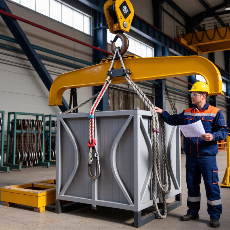
| Spreader Beams and Lifting Beams | ASME B30.20 for below-the-hook lifting devices; ASME BTH-1 for design category and service class where applicable. | Use the marked rated load and specified load distribution. The capacity can change with lifting-point spacing, sling angle, beam orientation, and attachment configuration. | Verify top and bottom connection capacities, center of gravity, beam length, headroom, deflection limits, and the capacity of the crane and supporting rigging. | Nameplate with rated load and configuration limits, visible weld quality, certified lifting points, sound pins and fittings, and documented design or proof-test information. | Check for cracks, deformation, corrosion, loose hardware, damaged welds, and missing safety devices. Use only the approved configuration and keep inspection records. |

.svg)