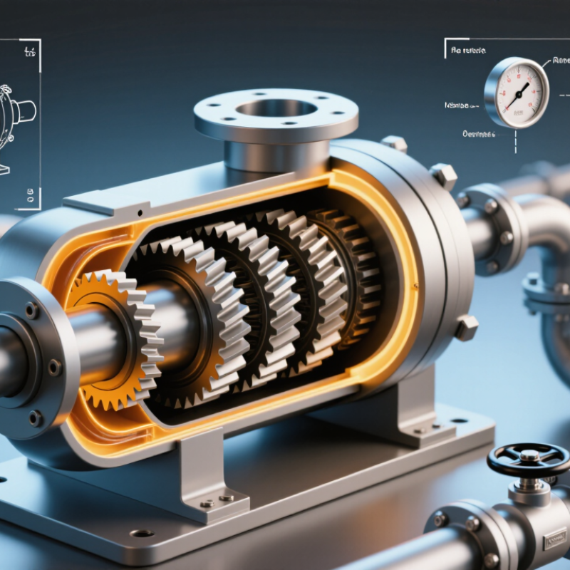
| Operating Principle and Pump Construction |
| Pump configuration | Positive-displacement, external gear pump; normally fixed displacement | Two externally meshing gears rotate inside a close-clearance housing. Fluid enters the suction side, is carried around the outside of the gears, and is discharged when the gear teeth re-mesh. | Choose this configuration when a compact, mechanically simple pump is required for clean or moderately filtered liquids with predictable flow. | Hydraulic power units, lubrication systems, fuel transfer, process dosing, and polymer or resin circulation. |
| Helical gear profile | Angled teeth with continuous or progressive tooth engagement | Helical teeth engage gradually rather than across the full tooth width at once. This generally reduces pressure pulsation, vibration, and operating noise compared with a straight-tooth design of similar size. | Select a helical profile when low noise, smoother flow, and reduced vibration are more important than the simplest possible gear geometry. | Machine tools, indoor hydraulic equipment, metering skids, lubrication packages, and noise-sensitive installations. |
| Flow characteristic | Nearly proportional to shaft speed; actual flow is reduced by internal slip | The theoretical flow is calculated from displacement and speed. Clearances, viscosity, pressure, and temperature determine the difference between theoretical and delivered flow. | Use a variable-speed drive or a bypass valve for flow adjustment. Do not regulate a positive-displacement pump by dead-heading the discharge. | Constant-flow lubrication, controlled transfer, hydraulic circuits, and low-to-moderate accuracy dosing. |
| Pressure protection | External relief valve or pressure-limiting device required in most systems | Because the pump continues displacing fluid while rotating, a blocked discharge can cause a rapid pressure rise and damage the pump, drive, piping, or seals. | Install a relief valve close to the pump discharge and size it for the pump capacity and maximum allowable system pressure. | All closed-discharge or valved hydraulic and process systems. |
| Key Technical Data for Initial Sizing |
| Displacement | Approximately 0.2–200 cm³/rev for common industrial external gear pump ranges | Displacement is the theoretical volume moved per revolution. Larger displacement produces more flow at the same shaft speed. | Start with the required flow and available speed. Select a displacement that meets the duty without exceeding the recommended speed or pressure. | Small metering and lubrication pumps through medium-duty hydraulic and process-transfer units. |
| Theoretical flow equation | Qth (L/min) = Vg (cm³/rev) × n (rpm) ÷ 1,000 | Example: a 10 cm³/rev pump at 1,500 rpm has a theoretical flow of 15 L/min before accounting for volumetric losses. | Estimate delivered flow using volumetric efficiency: Qactual = Qth × ηv. Confirm final values with the pump performance curve. | Hydraulic circuit calculations, preliminary pump selection, and motor-speed matching. |
| Typical flow range | Approximately 0.3–300 L/min, depending on displacement and speed | Actual capacity depends on pump size, fluid viscosity, pressure differential, and allowable rotational speed. | Specify both normal and maximum flow. Allow sufficient margin, but avoid oversizing because excess flow creates heat and may require throttling. | Hydraulic power packs, oil circulation, fuel transfer, coating systems, and process-fluid handling. |
| Typical rotational speed | Approximately 300–3,000 rpm; some designs operate outside this range | Speed determines theoretical flow and affects noise, wear, inlet conditions, and fluid shear. Maximum speed is pump- and fluid-specific. | Use slower speeds for high-viscosity fluids and difficult suction conditions. Check minimum speed for adequate lubrication and stable delivery. | Electric motor drives, variable-frequency drives, engine-driven systems, and servo-controlled equipment. |
| Operating pressure | Common working range: approximately 10–250 bar; some specialized designs are rated higher | Pressure capability depends on housing strength, bearing arrangement, clearances, shaft loading, fluid temperature, and service life requirements. | Separate continuous pressure, intermittent pressure, and peak pressure in the specification. Never select by maximum pressure alone. | Industrial hydraulics, lubrication circuits, fuel systems, and moderate-pressure process transfer. |
| Pressure differential | Often specified from approximately 5–200 bar for industrial duties | Pressure differential is the discharge pressure minus the suction pressure. It directly influences torque, leakage, heat generation, and volumetric efficiency. | Calculate pressure loss in pipes, filters, valves, coolers, and nozzles before choosing the pump rating. | Closed-loop circulation, hydraulic actuators, filtration systems, and transfer lines. |
| Volumetric efficiency | Commonly about 85–98%, depending on pressure, speed, viscosity, and internal clearances | Higher pressure and lower viscosity usually increase internal slip. Appropriate viscosity and operating speed help maintain delivered flow. | Use the manufacturer’s performance data at the actual pressure and viscosity rather than relying on a nominal efficiency value. | Flow-critical hydraulic systems, metering applications, and energy-efficient circulation systems. |
| Mechanical efficiency | Commonly about 85–97%, depending on design and operating point | Mechanical losses arise from gear meshing, bearings, seals, and viscous drag. Required input power rises with pressure and flow. | Size the motor for continuous duty, startup torque, fluid cold-start viscosity, and the highest expected pressure. | Motor-driven pump skids, hydraulic power units, and continuous process equipment. |
| Input power estimate | P (kW) ≈ Δp (bar) × Q (L/min) ÷ [600 × η] | For example, 100 bar at 20 L/min with 85% overall efficiency requires approximately 3.92 kW. | Use the calculated value as a preliminary estimate and include an appropriate service margin for starting and transient conditions. | Motor selection, drive sizing, energy estimation, and thermal-load calculations. |
| Fluid and Environmental Compatibility |
| Recommended fluid viscosity | Typical operating range: approximately 10–1,000 cSt; the precise range is design-specific | Higher viscosity can improve sealing and reduce slip, but it increases startup torque, suction losses, and frictional heating. | Check viscosity at startup and operating temperature. Confirm the minimum viscosity at maximum temperature and the maximum viscosity at the coldest startup. | Hydraulic oils, lubricating oils, fuels, polymers, resins, adhesives, and other lubricating liquids. |
| Low-viscosity liquids | Water-like or solvent-like fluids require special evaluation | Low-viscosity liquids can pass through internal clearances more easily, reducing efficiency and potentially increasing wear or corrosion. | Verify material compatibility, clearances, seal design, corrosion resistance, lubrication properties, and allowable speed before use. | Water-glycol fluids, light fuels, solvents, and low-viscosity chemical liquids when specifically approved. |
| Fluid temperature | Common industrial range: approximately -20°C to 150°C; wider ranges require special materials and seals | Temperature changes viscosity, seal performance, clearances, lubrication quality, and vapor pressure. | Specify minimum, normal, and maximum fluid temperature. Consider heating for high-viscosity liquids and cooling for continuous high-pressure service. | Outdoor hydraulic units, hot oil circulation, process heating systems, and temperature-controlled transfer. |
| Cleanliness and filtration | Clean, filtered fluid is strongly preferred; filtration often falls within approximately 5–25 μm for hydraulic service | Particles can damage gear teeth, bearings, shaft seals, and close internal clearances. The suitable filter rating depends on the pump and system. | Use the fluid cleanliness class and filter specification recommended for the application. Protect the suction side from blockage and excessive pressure loss. | Hydraulic systems, lubrication packages, precision machinery, and recirculating oil systems. |
| Seal and material compatibility | Common materials include cast iron, steel, stainless steel, bronze, and elastomers selected for the fluid | Material selection affects corrosion resistance, wear resistance, temperature capability, and chemical compatibility. | Provide fluid composition, additives, concentration, temperature, and pressure when requesting a final selection. Do not assume one seal material suits every fluid. | Chemical transfer, food-related process equipment, fuel handling, aggressive fluids, and high-temperature service. |
| Application Fit, Advantages, and Limitations |
| Main advantages | Compact construction, good repeatability, high starting torque capability, and smooth operation relative to straight-tooth gear pumps | The positive-displacement action provides predictable flow, while the helical tooth form can reduce pulsation and noise. | Choose a helical external gear pump when compact size, moderate-to-high pressure, and steady flow are priorities. | Hydraulic power units, machine tools, lubrication systems, fuel transfer, and process skids. |
| Noise and pulsation | Generally lower than comparable straight-tooth external gear pumps, but still dependent on speed, pressure, mounting, and inlet conditions | Gradual tooth engagement reduces abrupt changes in trapped volume and flow. Poor inlet design or excessive speed can still create noise and cavitation. | Use a properly sized suction line, avoid sharp inlet restrictions, maintain adequate inlet pressure, and isolate vibration where necessary. | Indoor machinery, mobile equipment, laboratory skids, and noise-sensitive production areas. |
| Self-priming capability | Often good with suitable lubricating fluids and a correctly designed suction line | Internal clearances allow the pump to create suction, but dry running, excessive lift, air leakage, or high fluid viscosity can prevent reliable priming. | Confirm allowable suction lift, startup conditions, priming procedure, and dry-run limits. Flooded suction is preferable for difficult fluids. | Lubricating-oil transfer, fuel systems, tank-mounted units, and intermittent-duty equipment. |
| Shear sensitivity | Generally suitable for many oils and moderately shear-sensitive liquids; fluid-specific testing may be required | Gear meshing and narrow clearances can expose the fluid to shear and local heating, especially at high speed or with high viscosity. | Reduce speed, control temperature, and confirm the fluid’s shear stability when handling polymers, emulsions, or structured liquids. | Resins, coatings, adhesives, polymers, inks, and specialized process liquids. |
| Solids handling | Limited; normally intended for clean or well-filtered liquids | Unfiltered particles can score the housing, damage gear teeth, block clearances, and accelerate seal and bearing wear. | Use upstream filtration or select a different pump technology if the liquid contains abrasive particles, large solids, or fibrous material. | Filtered oils and process liquids; generally unsuitable for raw slurries without special design. |
| Best-fit applications | Steady flow, moderate-to-high pressure, clean lubricating liquids, and compact installations | The pump delivers flow in proportion to speed and can operate over a broad range of industrial duties when correctly sized. | Prioritize this pump type where efficiency, compactness, repeatable flow, and lower pulsation are required. | Hydraulic power units, lubrication, fuel and oil transfer, metering, filtration, cooling, and process circulation. |
| Applications requiring caution | Highly abrasive slurries, unfiltered liquids, dry-running service, very high free-gas content, and extreme low-viscosity fluids | These conditions can cause rapid wear, loss of prime, cavitation, reduced efficiency, or seal failure. | Consider a lobe, screw, diaphragm, centrifugal, or other pump technology when the fluid or duty exceeds external gear pump limits. | Wastewater with solids, abrasive mineral slurries, gas-rich liquids, and fluids with poor lubricity. |
| 2026 Selection Checklist |
| Required operating data | Flow, discharge pressure, suction pressure, fluid viscosity, temperature, density, speed, duty cycle, and fluid composition | These variables determine displacement, torque, materials, seals, speed limits, heating, and expected service life. | Collect normal, minimum, maximum, startup, and upset conditions before comparing pump options. | Every new pump installation, replacement, retrofit, and process change. |
| Final verification | Performance curve, relief-valve setting, NPSH or inlet-pressure requirement, motor power, shaft torque, seal compatibility, and service factor | A pump that meets nominal flow may still fail if the inlet pressure, torque, temperature, or materials are unsuitable. | Request a duty-point confirmation and verify the complete pump, motor, coupling, relief valve, filter, piping, and control arrangement as one system. | Commissioning, equipment upgrades, energy optimization, and reliability-focused maintenance planning. |

.svg)