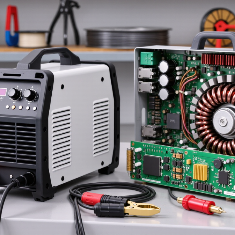
| Inverter IGBT welder | An arc-welding power source that uses an inverter circuit with insulated-gate bipolar transistors (IGBTs) to control electrical power. | It converts incoming electrical power into a controlled welding output. The inverter switches power at high frequency, allowing the machine to use a smaller transformer than a traditional line-frequency design. |
| Input rectifier | A circuit that converts incoming alternating current (AC) into direct current (DC). | Rectifier components turn the input AC into DC for the inverter stage. The exact input voltage and phase depend on the welder model and its rated supply. |
| IGBT switching stage | A set of electronic switches that rapidly turns electrical power on and off. | The control circuit drives the IGBTs in a switching pattern. Pulse-width modulation is commonly used to regulate the power delivered to the welding circuit. |
| High-frequency transformer | A transformer that changes voltage and current levels while providing electrical isolation in many designs. | It receives the inverter’s switched, high-frequency power and transforms it to a voltage suitable for the machine’s welding-output stage. High-frequency operation enables a more compact transformer than a traditional mains-frequency transformer. |
| Output rectifier and filtering | Components that convert the transformer output into the required welding current and help smooth it. | In many DC-output welders, output rectifiers convert the transformed waveform into DC. Filtering components reduce unwanted ripple before power reaches the welding terminals. |
| Control and feedback | Electronic circuits that monitor operating conditions and regulate the welding output. | Feedback from the output helps the control circuit adjust switching to maintain the selected current as welding conditions change, within the machine’s rated operating limits. |
| Welding output | The current and voltage supplied between the electrode and the workpiece to establish and maintain an arc. | The operator selects settings supported by the machine. The resulting arc melts the electrode and/or base metal, depending on the welding process and consumables used. |
| Common processes | Many inverter power sources are designed for processes such as stick (MMA/SMAW), TIG (GTAW), or MIG/MAG (GMAW), depending on the model. | Process capability depends on the machine’s output characteristics, controls, accessories, and rated duty cycle; not every inverter IGBT welder supports every process. |
| Typical advantages | Compact size, lower weight than many conventional transformer-based units, and electronic output control. | High-frequency switching makes smaller magnetic components practical. Actual efficiency, portability, and performance vary by design, input supply, settings, and operating conditions. |
| Operating considerations | Input-power requirements, ventilation, duty cycle, and correct polarity or process setup. | Use a supply and protective equipment that meet the welder’s rating. Keep cooling passages clear, observe the specified duty cycle, and follow the operating manual and applicable safety practices. |

.svg)