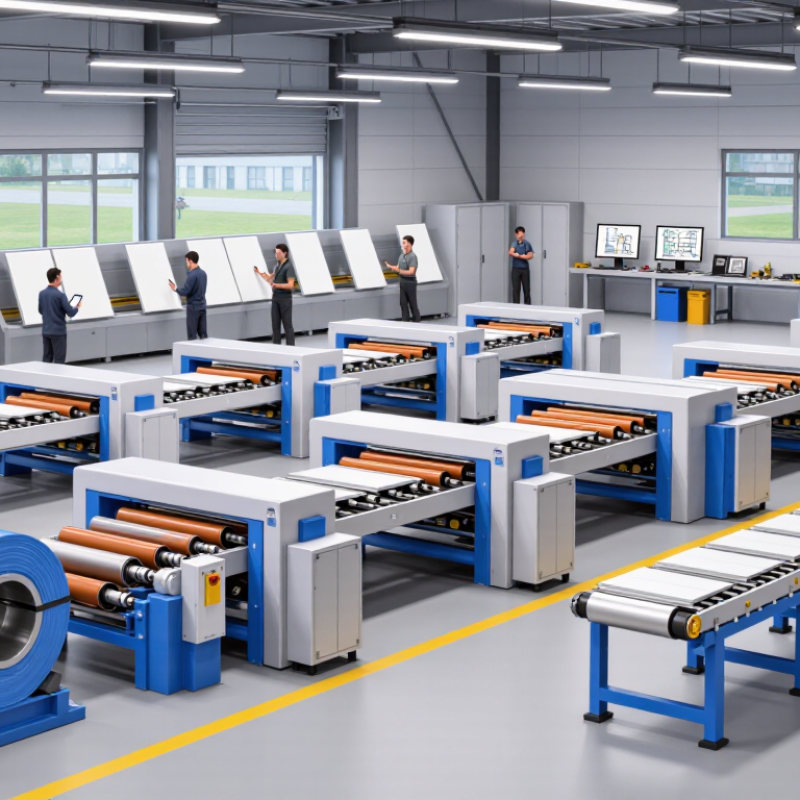
| Machine Definition | Continuous cold-forming production line | A roof sheet roll forming machine gradually shapes a metal coil into a specified roofing profile by passing it through a series of forming rollers. | Choose a machine designed for the exact roof profile, sheet thickness, and effective covering width required. |
| Common Roofing Materials | Galvanized steel, pre-painted steel, galvalume-coated steel, and aluminum | The machine forms corrosion-resistant or coated metal coils without heating the material. | Roller materials and forming settings should be compatible with the selected metal and surface coating. |
| Typical Material Thickness | Approximately 0.30–0.80 mm for many building roof applications | This is the usual range for lightweight and medium-duty profiled roofing sheets. | Confirm the actual thickness range before ordering because roller geometry and drive capacity depend on it. |
| Coil Input Width | Commonly about 900–1,250 mm, depending on the finished profile | The input width is the width of the flat coil before it passes through the forming process. | Input width is not the same as the effective covering width of the finished roof sheet. |
| Effective Covering Width | Often approximately 750–1,100 mm | This is the usable installed width after side laps or profile forming are taken into account. | Match the covering width with the building design and required roof panel layout. |
| Production Speed | Approximately 8–25 m/min, depending on profile and configuration | Production speed indicates how quickly the formed sheet exits the line, usually excluding loading and coil-change time. | Higher speed may reduce production time but can require stronger feeding, cutting, and control systems. |
| Forming Stations | Typically 10–20 roller stations | Each station makes a small part of the final shape, allowing the sheet to be formed progressively. | Complex profiles generally need more stations to reduce distortion and protect the coated surface. |
| Drive System | Electric motor with gearbox and synchronized roller shafts | The drive system transfers torque to the forming rollers and maintains a consistent feed rate. | Check motor capacity, shaft diameter, gearbox quality, and synchronization performance. |
| Cutting Method | Hydraulic or electric automatic cut-to-length system | The cutting unit separates finished panels after the programmed length is reached. | A flying or stop-and-cut configuration may be selected according to the required production speed. |
| Length Setting | Digital length control through a programmable control system | The operator can enter the desired panel length and production quantity before forming begins. | Actual cutting accuracy depends on encoder calibration, material condition, and machine adjustment. |
| Length Accuracy | Commonly around ±1–2 mm under suitable operating conditions | This describes the typical difference between the programmed panel length and the actual cut length. | Accuracy should be verified with test panels and may vary with speed, thickness, and profile design. |
| Control System | PLC-based control panel with touchscreen or digital interface | The system manages feeding, forming speed, panel length, cutting, counting, and emergency functions. | Select an interface that supports clear parameter adjustment, fault messages, and operator access control. |
| Installed Power | Often approximately 5–15 kW, excluding or varying with auxiliary equipment | Total power depends on the main drive, hydraulic cutting unit, decoiler, and other accessories. | Verify the local voltage, frequency, phase configuration, and available electrical capacity. |
| Decoiler Capacity | Commonly about 3–10 metric tons | The decoiler supports the metal coil and feeds it into the forming machine at a controlled rate. | Capacity should exceed the maximum coil weight while matching the coil inner and outer diameters. |
| Typical Line Components | Decoiler, guiding unit, roll forming section, cutting unit, control cabinet, and run-out table | These components work together to unwind, align, form, cut, and collect the finished roof panels. | Confirm whether feeding, automatic stacking, packaging, and other auxiliary units are included. |
| Finished Roof Profiles | Corrugated, trapezoidal, ribbed, and other custom-designed profiles | Different roller sets produce different rib shapes, heights, pitches, and overlap details. | A dedicated roller tooling set is generally required for each distinct roof profile. |
| Surface Protection | Protective film, polished rollers, accurate alignment, and controlled forming pressure | These measures help reduce scratches, dents, and coating damage during production. | Surface quality is especially important for pre-painted and decorative roofing materials. |
| Operator Requirements | Usually one trained operator, with additional support for coil handling and stacking | The operator monitors coil feeding, machine settings, panel quality, and safe operation. | Training should cover setup, profile adjustment, emergency stops, maintenance, and workplace safety. |
| Maintenance Items | Roller alignment, lubrication, fastener inspection, sensor checking, and hydraulic maintenance | Regular maintenance helps preserve forming accuracy and reduces unplanned downtime. | Keep replacement sensors, seals, cutting blades, and commonly used fasteners available. |
| Primary Benefits | Continuous production, repeatable profiles, reduced manual work, and flexible panel lengths | The machine improves consistency compared with manually shaping individual sheets. | Overall productivity depends on coil supply, changeover time, operator skill, and downstream handling. |

.svg)