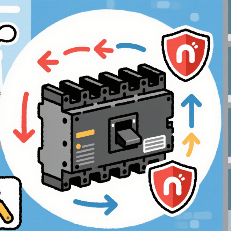
| Moulded insulating case | Encloses and supports the breaker’s internal parts, including its contacts and trip components. | Helps provide electrical insulation and mechanical protection. | The breaker must be selected for the installation environment and used within its rated specifications. |
| Fixed and moving contacts | Make or interrupt the current path when the breaker is switched on or trips. | Disconnect the circuit when an opening operation is triggered. | Contact wear depends on operating conditions, switching frequency, and fault duty. |
| Operating mechanism and trip-free action | Opens and closes the contacts and releases them when the trip system operates. | Allows the breaker to interrupt a circuit even if the handle is held in the ON position. | A tripped breaker generally requires the prescribed reset procedure before it can be closed again. |
| Thermal overload release | In a thermal-magnetic design, a temperature-responsive element reacts to sustained overcurrent. | Trips the breaker to help protect conductors and equipment from prolonged overload heating. | Thermal response is time-dependent; the trip curve and ambient conditions affect operation. |
| Magnetic instantaneous release | In a thermal-magnetic design, a magnetic element responds rapidly to sufficiently high current. | Provides fast tripping for high-current short-circuit conditions. | Its operating threshold is determined by the breaker design and rating; it is not necessarily adjustable. |
| Electronic trip unit (where fitted) | Measures current and uses electronic circuitry to apply configured trip characteristics. | Can provide overload and short-circuit protection, with settings and features depending on the model. | Some units offer adjustable protection settings; settings must be coordinated with the system design. |
| Arc-control assembly | Guides and helps extinguish the electrical arc produced as contacts separate under load or fault conditions. | Supports reliable interruption and helps limit arc effects inside the breaker. | Breaking capacity is a specified rating and must be suitable for the prospective fault current at the installation point. |
| Terminals and conductor connections | Connect the breaker to the supply and load conductors or busbars. | Provide the electrical interface for circuit protection and isolation. | Conductor size, terminal compatibility, and tightening requirements should follow the breaker’s instructions. |
| Manual switching and isolation | Allows an operator to open or close the circuit using the breaker’s operating handle. | Provides a means of switching the circuit and, when open, separating the circuit contacts. | A breaker should not be treated as a substitute for safe isolation and verification procedures. |

.svg)