| Ball-Lock Quick Coupler | A sleeve-operated coupler uses locking balls to secure a plug. Internal valves normally close when the coupling is disconnected. | Compressed air, water, hydraulic fluid, and some process fluids | Brass, stainless steel, carbon steel, engineering polymers | Approximately 1/8 to 1 inch nominal connection sizes | Commonly from low pneumatic pressures to several hundred bar in hydraulic designs; rating depends on the series and size | Fast manual connection, broad availability, and simple operation | Confirm plug profile, valve configuration, flow direction, seal material, and pressure rating before interchangeability is assumed |
| Push-to-Connect Tube Fitting | Tubing is pushed through a collet and retained by gripping teeth. A seal is released by pressing the release ring. | Compressed air, inert gases, water, and low-pressure instrumentation service | Polymer body, nickel-plated brass, stainless steel, elastomer seals | Commonly 4 to 16 mm tubing or approximately 1/8 to 1/2 inch tubing | Often suitable for pneumatic systems up to approximately 10 bar, subject to temperature and tubing specifications | Tool-free assembly, compact design, and quick maintenance | Cut tubing squarely, insert it fully, and verify compatibility between tubing material, outside diameter, and seal compound |
| Flat-Face Hydraulic Coupler | Matched male and female halves connect with a sleeve or threaded locking mechanism. Flat valves minimize fluid loss and air inclusion during connection. | Hydraulic oil and other compatible hydraulic fluids | Hardened carbon steel, stainless steel, zinc or corrosion-resistant plating | Commonly 1/4 to 2 inches nominal connection sizes | Many designs are rated from approximately 200 to 450 bar; exact limits depend on size, series, and application | Low spillage, reduced contamination, and good suitability for mobile hydraulic equipment | Coupling must be fully locked; pressure should generally be removed before connection unless the design is specifically rated for connection under pressure |
| Threaded Hydraulic Coupler | Male and female halves are joined by manual threads, creating a mechanically secure connection for demanding hydraulic circuits. | Hydraulic oil, lubricants, and compatible industrial fluids | Carbon steel and stainless steel with elastomeric sealing elements | Commonly 1/4 to 1 inch nominal connection sizes | Frequently used in medium- to high-pressure systems, with ratings commonly reaching several hundred bar | High resistance to vibration and accidental uncoupling | Connection takes longer than sleeve-operated types; threads, torque, cleanliness, and seal condition require careful inspection |
| Dry-Break Coupler | Specially shaped valves close before the coupling separates, limiting liquid release and reducing vapor or air entry. | Chemicals, fuels, solvents, water, and other process liquids compatible with the selected materials | Stainless steel, aluminum, brass, fluoropolymers, and application-specific elastomers | Commonly 1/2 to 4 inches nominal connection sizes | Varies widely by design; many industrial models operate from low pressure to several tens of bar | Very low leakage, improved operator safety, and reduced environmental exposure | Check chemical compatibility, vapor pressure, allowable pressure drop, grounding requirements, and cleaning procedures |
| Cam-and-Groove Coupling | Two cam arms clamp over the adapter groove. No wrench is normally required for connection or disconnection. | Water, agricultural liquids, powders with suitable hose systems, and selected chemicals | Polypropylene, stainless steel, aluminum, brass, and ductile materials | Commonly 1/2 to 6 inches nominal connection sizes | Often used in low- to medium-pressure transfer service; ratings may range from approximately 5 to 20 bar depending on size and material | Very fast hose connection and convenient frequent transfer operations | Not normally recommended for compressed gas; secure the cam arms and verify that the gasket and adapter profile match |
| Bayonet Coupling | Male and female parts engage with a push-and-twist movement and lock through slots, pins, or lugs. | Air, water, fuel, electrical-fluid interfaces, and specialized industrial media | Aluminum, brass, stainless steel, engineering polymers | Commonly below 1 inch, with larger sizes available for specialized applications | Application-dependent; many designs are intended for low- to medium-pressure service | Quick alignment, compact installation, and positive mechanical locking | Inspect locking lugs and alignment marks; do not force the connection if the coupling is contaminated or misaligned |
| Multi-Line Quick Connector | Several fluid, pneumatic, hydraulic, or electrical circuits are connected simultaneously through one keyed interface. | Hydraulic oil, compressed air, coolant, electrical signals, and mixed utility systems | Aluminum, steel, stainless steel, thermoplastics, and plated components | Usually designed around application-specific ports rather than one universal size range | Each circuit has its own pressure and flow rating; the lowest-rated circuit limits the assembly | Reduces connection time, prevents cross-connection through keying, and simplifies equipment changeover | Evaluate alignment tolerance, circuit identification, residual pressure, service access, and the effect of connecting one circuit before another |
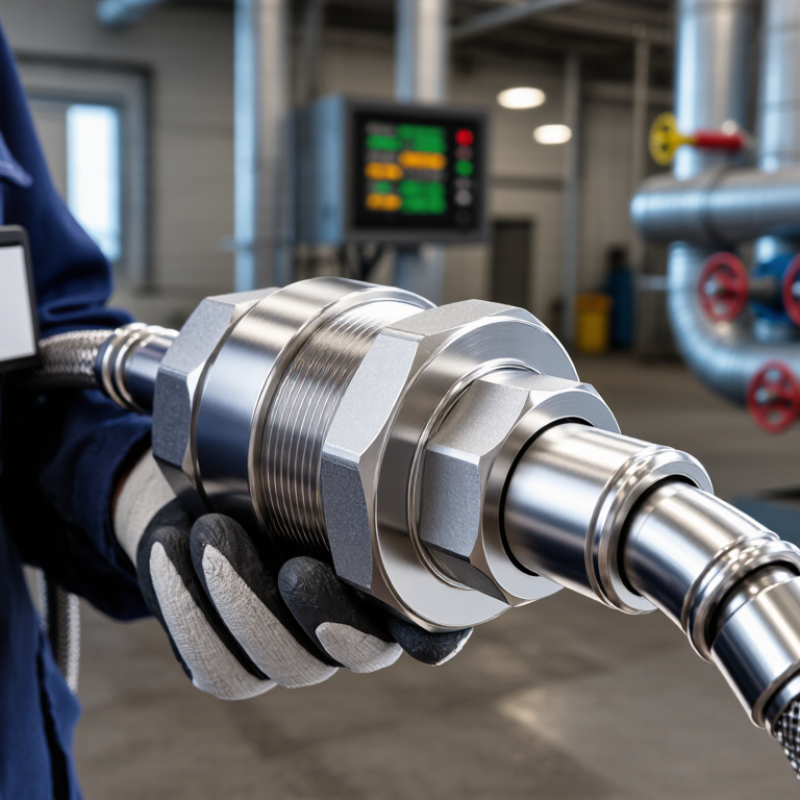
| Operating Principle | A quick-connect fitting consists of a plug and a coupler. The coupler normally includes a locking mechanism and may include one or two internal shut-off valves. When the two halves are connected, the valves open and allow fluid or gas to pass. When they are separated, the valves close in self-sealing designs to help limit leakage and contamination. |
| Global Buyer Checklist | Confirm the connection profile, nominal size, thread standard, pressure and temperature ratings, flow capacity, seal material, body material, media compatibility, applicable documentation, packaging requirements, and regional conformity requirements. A fitting with the same nominal size may not be interchangeable if its profile, thread form, valve arrangement, or locking system differs. |
| Data Qualification | The pressure, temperature, size, and media ranges shown are typical industry-use ranges rather than universal limits. Always use the manufacturer's technical documentation and system safety calculations for final selection. |

.svg)